Senseo Boiler: Heat and Electricity
This post is part of the Senseo series:
- Senseo Prelude
- Senseo Electricity Basics 1
- Senseo Electricity Basics 2: Generation
- Senseo Electricity Basics 3: Grid to Wall Socket
- Senseo Boiler: Heat and Electricity
- Senseo Boiler: Sensing Temperature
- Senseo Boiler: Sensing Temperature Part 2
- Senseo Boiler: Safety
- Senseo Boiler: Brewing
- What is Plastic?
- PCB - Printed Circuit Boards: Fundamentals 1
- PCB Fundamentals 2: MOSFET Transistors
- PCB Fundamentals 3: CMOS Logic
- PCB Fundamentals 4: Combinational v Sequential Logic
- PCB Fundamentals 5: D-Latch
- PCB Fundamentals 6: Clocks & Flip-Flops
- PCB Microcontroller Subsystems: CPU core
- PCB Microcontroller Subsystems: GPIO
- Senseo GPIO Button Example
- PCB Microcontroller Subsystems: ADC (Conceptual)
- Senseo Interlude: Considering Quality
- PCB Microcontroller Subsystems: RAM and FLASH memory
Big Picture
This next chapter is one I’m very much quite interested in, as truly the only way I can imagine making water heat up is by creating a fire and putting a pot of water from a stream on it.
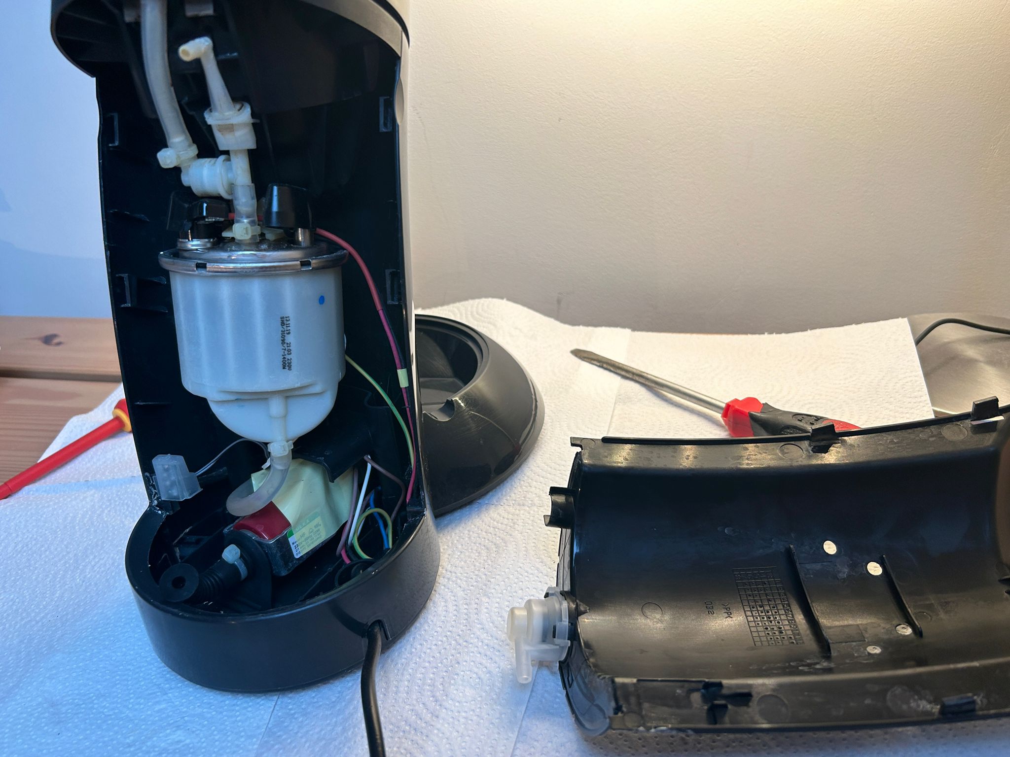
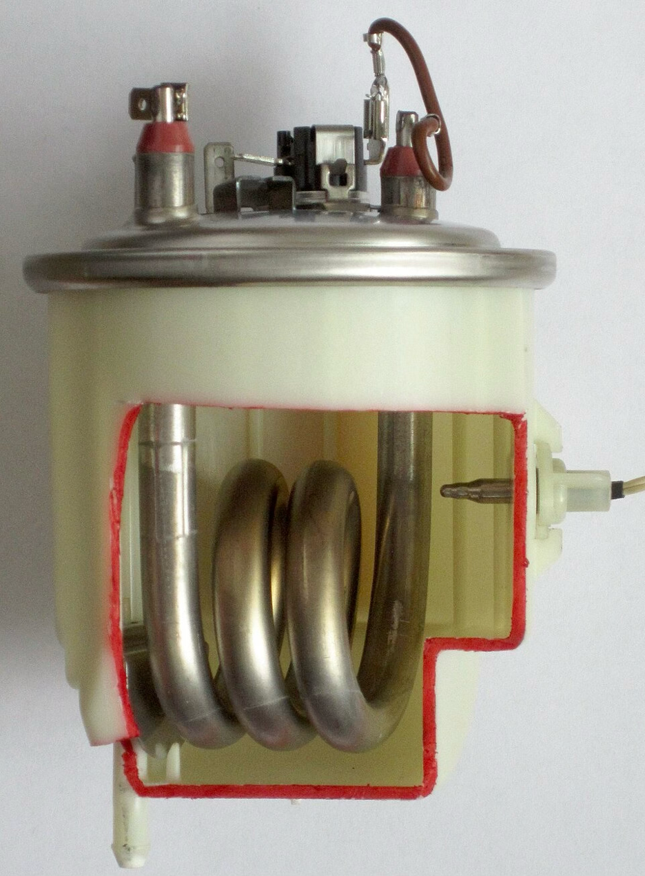 When we take apart the Senseo machine, this is also the first thing we see. It’s a big white container in the middle of the machine, connected to valves and the pump (at the bottom). Luckily I didn’t have to cut my boiler open to see this, as our good friend Wikipedia has an image showing this magnificent sight. This whole outer plastic is usually filled with water.
But now to the real question, how do we go from cold water to warm or even hot water? Going from nothing to something? Perhaps we can again start from atoms and molecules. Water is made from H2O atoms, and a lot of them (molecules) make up a body of water. As seen in early physics classes, when water is cold, these molecules move slowly, when heated they move faster. So the idea of heating (or boiling) water is just to make the molecules move fast enough. If I’d use the caveman method, I’d collect some wood, start a fire through friction. When wood is burning, the chemical energy the wood holds is released as heat upon combining with oxygen. This heat rises and touches the pot, into the material of it. That material itself gets hot and warms the water.
A typical problem with this method is that most energy that’s created gets lost, only a little touches the pot and even less results in accomplishing the goal of heating water (indirect heating). The goal is therefore to capture all that released energy.
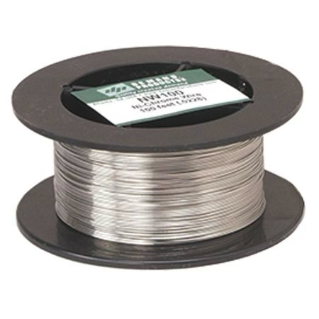
Resistive heating (or joule heating) on the other hand is the process where electricity, being moving electrons, are forced through material that resist flow. When the electrons bump into the atoms inside that conductor, friction is created at the atomic level and heat is created. So all that is needed to do this, is attaching the electric wire (coming from the wall) to a sort of tube, made of nichrome (=80% nickel, 20% chromium) that has the characteristics to resist electrons but not melt. With such a material, the electricity flowing through will cause perfect and constant heating, making the H2O molecules in turn move faster. This is the same exact idea used for toaster wires or tea kettles. As such we’re heating water directly, since it’s not the air or pot that’s heated and in turn heats the water, but it’s a wire going through water (such as seen in the boiler) that heats the water immediately.
What therefore actually happens is, electricity (as AC) comes from the wall at 230V into the Senseo machine in the form of two wires, live and neutral. These are connected to the two terminals on the boiler (see red tips). Each terminal gets one of the wires, making the heater tube one big resistor. So when the machine wants heat, it connects live to the heater and the current flows through.
This explains also why the Senseo has multiple power circuits. There is one high voltage AC circuit, going directly to the boiler (since it eats power), while the electrical parts such as PCB and microcontroller need a separate low voltage DC that’s controlled and gives 5V (or 12V). Depending on the Senseo model, the pump itself will either be also on the DC, or on a lower voltage AC (separate circuit). This is because the pump is an electromechanical device requiring control and timing.
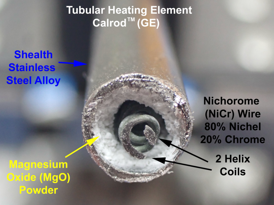 The tube we saw in the boiler-picture, however, isn’t what’s carrying the electricity, it’s a protective casing that has an insulated heater wire made of nichrome inside it. This wire doesn’t touch the stainless steel tube at all, but is insulated by Magnesium Oxide powder (MgO). Heat travels through this insulation quite easily, since MgO blocks the electricity but is still thermally conductive. No electrons can ever enter the water.
My first question when learning about this Nichrome helping with resistance and resulting in heat was, “what about Ohm’s law then?” Since Ohm’s law shows this relation between resistance, voltage and current, doesn’t that cause issues for the electricity we’re connecting to this?
Well the idea of Ohm’s law is this. If we think of electricity as water flowing through a pipe, then the water flow (measured in ampere per seconds) is current (I), the pressure pushing the water is voltage (V) and the narrowness of the pipe is the resistance (R). Ohm’s law merely describes the relationship between these three: Voltage (push) = Current (flow) * Resistance (obstacle). Or turned around, current is voltage divided by resistance, meaning that more pressure results in more flow, but smaller pipe in less flow. Now if the wire is such that there’s a lot of resistance, such as Nichrome, the electrons move through and bump into atoms and vibrate as a result (=heating). Ohm’s law therefore just tells us what will happen and is used to predict how much current will flow through a wire, how much heat will be generated and so on.
Two terminals with red insulation
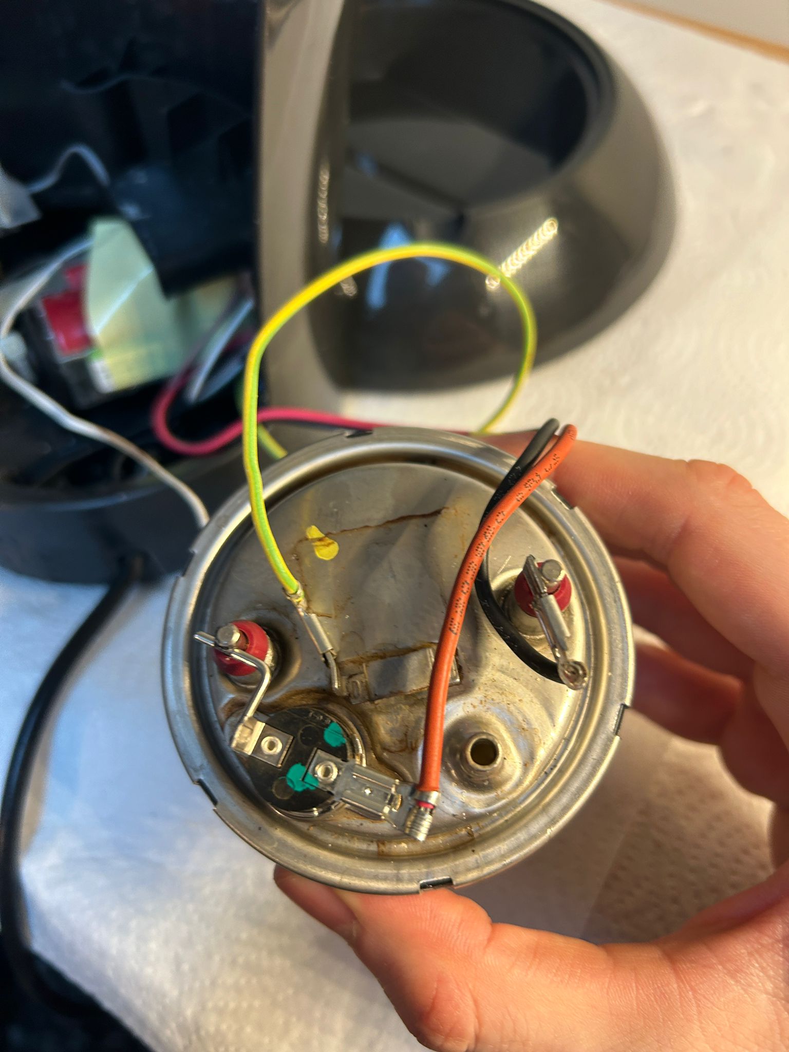
We’ve already identified the two red insulated terminals on top, but when opening up the Senseo, it appears there is actually three wires attached to these. Apparently, being the responsible engineers that they are, they also provide the boiler of an earth wire, which we see to be the yellow/green one attached on the left. This is purely a safety wire, so that if something breaks and the boiler becomes ‘live’, the current goes through this one to the ground and the circuit of my kitchen will be shut off by the breaker. You can kind of see it in the picture, where this green/yellow wire is actually directly attached to the metal top, not to an extension of the terminals.
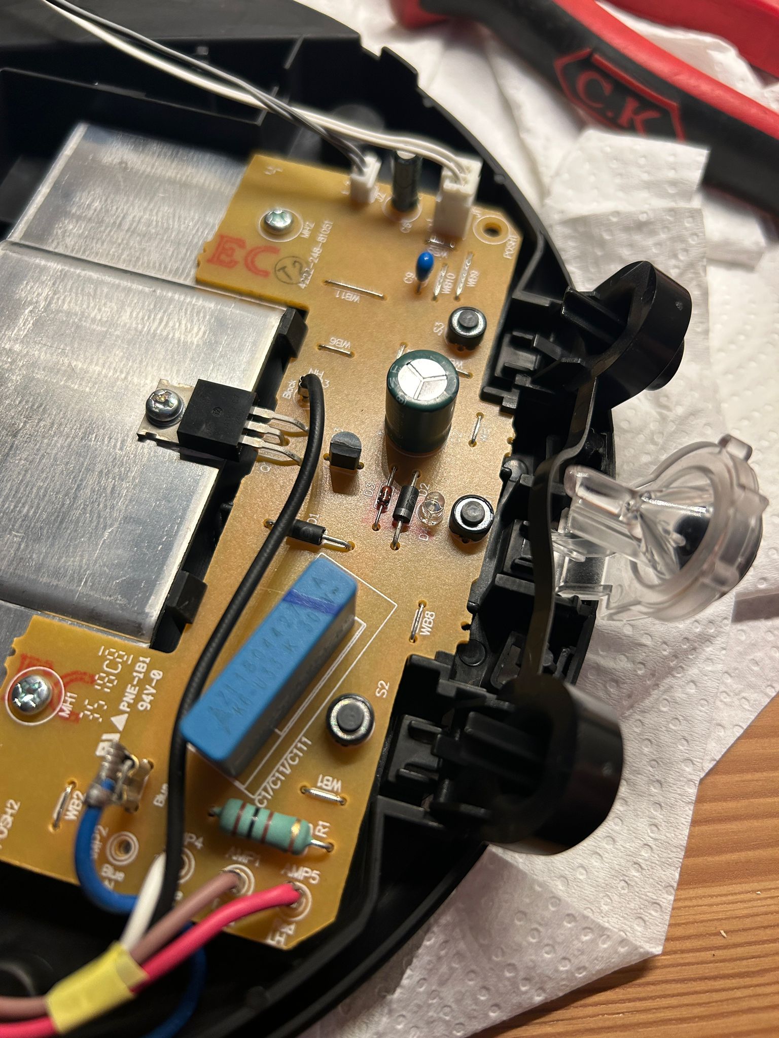
Then there’s also the live wire, which is the red one, and goes with high voltage AC (230V). As I show in the second picture, both the black and red wire come from the circuit board of the machine. So when the electricity enters the machine, it first goes through the relay (bridge controlling circuits) and then goes to the boiler, making it possible to have the user manipulate what happens when (more on this later).
The black wire is then the Neutral one, completing the circuit. Note that since these two wires are attached to separate terminals in order to complete the circuit, changing the terminal each is attached to won’t change anything, nothing will break or go wrong. The heater has no polarity (though there is a safety element apparently with the breaker being attached to the live side, so in terms of safety things will change).
A possible question here is why exactly the live wire needs to come from the panel control board (PCB) and not directly from the wall socket as it’s a separate high voltage circuit? I thought this might have been the case because the moment we turn on the device, we notice it starts heating. Nevertheless, when temperature reaches a certain threshold, or water is up, or even the fact that ‘on’ makes it heat, is all controlled by the PCB. So this red wire is attached to a relay, which is like a bridge that whenever the device rules that there needs to be warm water, connects the red wire to electricity.