PCB - Printed Circuit Boards: Fundamentals 1
This post is part of the Senseo series:
- Senseo Prelude
- Senseo Electricity Basics 1
- Senseo Electricity Basics 2: Generation
- Senseo Electricity Basics 3: Grid to Wall Socket
- Senseo Boiler: Heat and Electricity
- Senseo Boiler: Sensing Temperature
- Senseo Boiler: Sensing Temperature Part 2
- Senseo Boiler: Safety
- Senseo Boiler: Brewing
- What is Plastic?
- PCB - Printed Circuit Boards: Fundamentals 1
- PCB Fundamentals 2: MOSFET Transistors
- PCB Fundamentals 3: CMOS Logic
- PCB Fundamentals 4: Combinational v Sequential Logic
- PCB Fundamentals 5: D-Latch
- PCB Fundamentals 6: Clocks & Flip-Flops
- PCB Microcontroller Subsystems: CPU core
- PCB Microcontroller Subsystems: GPIO
- Senseo GPIO Button Example
- PCB Microcontroller Subsystems: ADC (Conceptual)
- Senseo Interlude: Considering Quality
- PCB Microcontroller Subsystems: RAM and FLASH memory
Bits and pieces
 Let’s now start with arguably the most intricate sections, the ones exploring printed circuit (or wiring) boards. In its essence, it functions as a fixed path for components to have connections to their counterparts. Instead of having wires connect the components electrically, the PCB does it via copper pathways. So most of the board is insulated. Remember from the boiler pipe that this refers to materials not allowing electrons to flow. Certain specifically directed tracks on the board are then made of copper to permit that flow.
Fire Retardant 4
The insulating material in the case of PCBs is fiberglass and epoxy, whose combination is also called FR4 - fire retardant [factor] 4. The idea with fiberglass is that glass is made into a kind of woven fabric that leads us to have thin fibers. So it’s literally just glass woven into microscopic threads. The result is a very strong, heat resistant and non-conductive material. The reason this is done is because glass on its own breaks easily, yet has the good qualities we seek for this board. Once molten glass is woven into fibers, however, it becomes extremely strong and flexible while retaining those attractive qualities.
Epoxy resin is a little more intricate, as it’s a type of hard plastic. But what is plastic? Well I wrote a little exploration on it. Polymer, these very long chains of small repeating molecules linked to each other, likewise have the quality of not conducting electricity while bringing the additional advantage of having a moldable design. In fact, epoxy resin isn’t just a polymer, but a thermosetting polymer, meaning that it’s a type of plastic that is first liquid and upon heating (or a chemical reaction) will become very hard and never again lose its shape (from newer heating). The result is a ceramic-like hard plastic.
The combination of the two leads to a reinforced plate that’s well insulated. A good analogy for this is reinforced concrete. Cement is hard but brittle (epoxy resin), steel rebars are strong but flexible (fiberglass), yet together they form something strong and rigid. FR4, our combined material, is as such electrically insulating, flame resistant, easily operable and holds copper very well, which makes it perfect for electronics.
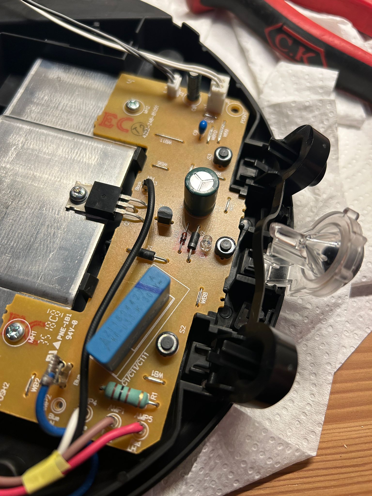
There are some additional layers aside from the FR4. The first is that of copper pathways carrying the electricity from component to component. Then, a sort of colored coating (brown or green) goes on top of the copper and prevents short circuiting. On the very top, then, we can see a silkscreen holding white printed text, labels and outlines of the components.
The big help of this board is the replacement of wiring for very intricate actions, creating a very neat and efficient place for essential electronic actions to take place. We find three different kinds of copper on the board, being power traces, signal traces and ground planes. The power traces have the simple task of carrying electricity from the power supply to a destination. Signal traces carry data or control signals, and ground planes are used to have a reference layer (other side of the board) and reduce electrical noise.
Data Through Voltage & Transistors
Personally, I get a bit confounded by the phrase ‘carry data or control signals’ for the signal traces. What does that mean? It kind of distracts me towards another topic I’m eager to explore, which is how people have managed to put music into the physical object of a vinyl record, which then plays when a needle goes through it.
Well PCB signal traces are just wires, which can do only one thing which is let electrical signals travel along them. An electrical signal is where changes in voltage are used and encoded with data. It is the equivalent of signaling with morse code and a flashlight, where ON, OFF and length are used to carry information. With the PCB, it’s the exact same idea, but with voltage. High voltage and low voltage are the two options, turning into 1’s and 0’s respectively and becoming binary digits (bits), the simplest unit of data.
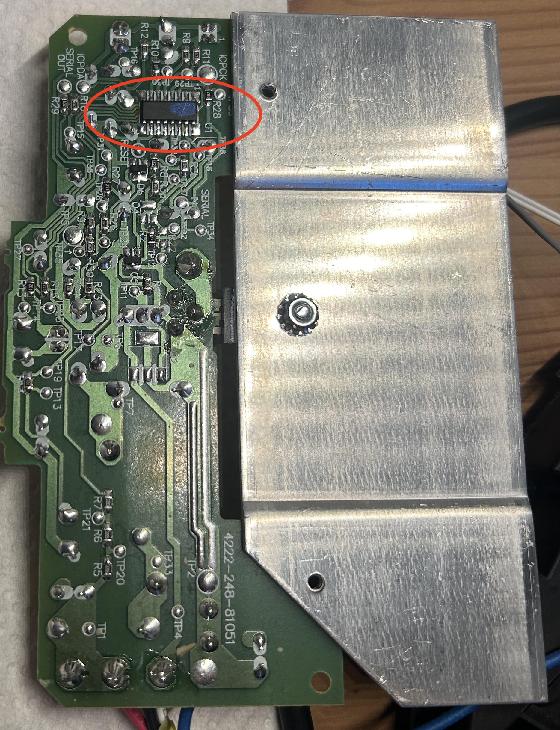 The place where such hardware changes become logic and mean something in the software sense, is the microcontroller (MCU). In our boiler section, we referred to the PCB like the body where all the wiring are connected, while MCU is the brain controlling the machine and the firmware inside the MCU is the memory (which the developer encodes). What gives the MCU such power is the ability to stack 100.000 to 1 million MOSFET transistors in it. This is the case in the Senseo machine, but in other appliances, or even say the smartphone, this goes up to billions.
These transistors are like tiny switches, turning the flow of electrons on or off, and causing voltage to rise and fall on the copper trace. Another chip at the other end of the trace picks this up and interprets the pattern. Data is therefore merely timed voltage changes. As we’ve seen, however, it isn’t really electrons that are flowing through the wire, as they just jiggle in place (think back to the pendulum swing). The changing current is what results in an electromagnetic wave travelling at nearly the speed of light.
Now different chips must understand each other, just like we agree on the morse code alphabet. The way chips do it is through Communication Protocols, which is the shared language (like USB, Ethernet, HDMI etc.). Chips are designed in a specific manner to be able to understand each other. If we have a microcontroller, the counterparty might be a sensor (temperature or light), a memory chip (like RAM), and so on. The microcontroller uses the transistors to switch the output pin to VDD (high voltage) or ground (low voltage). We’re not going to go into these communication protocols too much, as the Senseo doesn’t really use these but instead uses direct control signals (MCU pin voltage goes high —> Boiler on). Just be aware that these exist.
If we place these transistors in a certain order and connect them in an intelligent manner, we get logic gates. For instance the NOT gate where input is 1, so output becomes 0 and vice versa. It is by ordering and structuring these transistors into such logic circuits, and then ordering and structuring these logic circuits to interact with each other, that allows the machine to do any number of extremely complex tasks. All the while it still only uses high and low voltage as its tools. We’ll come back to the PCB itself later on and identify the different components on it. What’s more important to really get an understanding of why the machine is able to do anything, is to take our surgeon’s knife and go straight for the brain. To do this, we start by dissecting what this transistor really is, and will then go on to what kind of complex behavior can be achieved through them.