PCB Microcontroller Subsystems: ADC (Conceptual)
This post is part of the Senseo series:
- Senseo Prelude
- Senseo Electricity Basics 1
- Senseo Electricity Basics 2: Generation
- Senseo Electricity Basics 3: Grid to Wall Socket
- Senseo Boiler: Heat and Electricity
- Senseo Boiler: Sensing Temperature
- Senseo Boiler: Sensing Temperature Part 2
- Senseo Boiler: Safety
- Senseo Boiler: Brewing
- What is Plastic?
- PCB - Printed Circuit Boards: Fundamentals 1
- PCB Fundamentals 2: MOSFET Transistors
- PCB Fundamentals 3: CMOS Logic
- PCB Fundamentals 4: Combinational v Sequential Logic
- PCB Fundamentals 5: D-Latch
- PCB Fundamentals 6: Clocks & Flip-Flops
- PCB Microcontroller Subsystems: CPU core
- PCB Microcontroller Subsystems: GPIO
- Senseo GPIO Button Example
- PCB Microcontroller Subsystems: ADC (Conceptual)
- Senseo Interlude: Considering Quality
- PCB Microcontroller Subsystems: RAM and FLASH memory
Now we already kind of saw the ADC (analog to digital converter) in the boiler section where it was used to turn the voltage into a temperature in order to see how hot the boiler was at a given moment.
Recap NTC Thermistor
Perhaps to briefly revisit, what happens is that the boiler gets hot inside through the heating, resulting in the ability for electrons inside the NTC thermistor bead to move faster. And because the thermistor is essentially a semiconducting resistor, resistance inside is going down as temperature goes up (and vice versa).
A circuit is then added called the voltage divider, which turns this resistance into a voltage. We then saw some electricity basics, essentially the idea (if I remember correctly derived from either Kirchoff or Ohm’s law) was that since the same current flows through both resistors, the voltage divides proportionally to their resistance. The resistors share the voltage going from 5V to GND, and if the first resistor is a fixed measure, we can measure the point between R1 and R2 and figure out the resistance at R2 at a given moment. R2 in that instance represents the semiconductor that has a different resistance depending on the temperature inside the boiler.
From Voltage Divider to MCU
That voltage from the voltage divider now goes to a pin on the MCU. This is just one of the pins we see physically. The CPU now attaches the ADC to that pin (not the GPIO) through a multiplexer. Remember the pins on the MCU can switch roles depending on which function the MCU wants it to have. The reason the voltage from the voltage divider enters the MCU and directly goes to the ADC is because the GPIO is for digital inputs only (binary, discrete). Our voltage is entirely analog (continuous).
In fact, both a button press and the boiler temperature voltage are analog. The reason the button doesn’t need ADC and just goes to the GPIO for cleaning is that we simply want to know if it’s pressed or not. It’s functioning is only meaningful in a binary manner. So we can represent that meaning inside the machine simply by mimicking it through the binary signals electronics uses anyway. Meanwhile with the temperature voltage. We want pretty precise measurements and a way to represent values in a continuous way so that the MCU can make the proper decisions.
So the voltage enters the MCU and can be 0.83V, 2.53V etc. But the CPU cannot understand this as it’s first brought to the ADC. As we then also briefly mentioned in the boiler section, the ADC now turns this voltage into a number ranging from 0 (at 0V) to 1023 (5V - assuming a DC circuit with 5V max taken as reference voltage).
ADC Value
The ADC actually looks at the range between 0 and 5V and divides this into discrete buckets from 0-1023 (conceptually). It actually divides each step into Vref/1024. When it then sees a certain voltage from the voltage divider, it outputs eg. 170 out of 1023. This digital number the CPU is able to read.
MCU Reverse Engineering
And remember, the CPU is a simple block that stores, compares, adds, subtracts, multiplies, divides and follows instructions (firmware - if, then, else loops). It doesn’t know temperature or voltage meanings. The number given by the ADC, say 170, enters the CPU and just sits in a register (bunch of flip flops) for some time. As per instruction of the firmware, the CPU will assign the number to the firmware’s idea of a variable (eg. adc_value = 170).
We’re still inside the loop of what we saw in the boiler section, where I mentioned “The firmware essentially converts the ADC to V-out by (V-out = (ADC/1023)*V-ref)”. This is actually the next step inside the CPU. It again calculates the voltage from the voltage divider, but in reverse, on it’s own rules. For instance Vout = 170 / 1023 × 5 ≈ 0.83V.
It actually completely reverse engineers what the temperature was, because the next step, still inside the CPU, is that it uses the R-ntc formula we saw

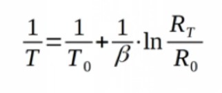
It thereby get the resistance number (its second transformation). As a third transformation, it turns this resistance number into a temperature number by, again, the formula we saw before, the beta equation
Note that these 3 transformations the CPU essentially does to reverse engineer what goes on in the outside world, and are merely numbers obtained through calculations. No real resistance is measured. The firmware merely contains the beta equation and through adders/comparators and so on the CPU calculates the resistance value from the ADC value and stores it again in a register.
Also note that we’re making assumptions here about how the CPU works. Since it’s entirely embedded within the machine and I have no access to the design, I’m merely exploring the way it could work. But chances are these equations are skipped and the machine has a simple lookup table in its firmware. I just don’t know.
Decision Making
What happens now is the decision making. This is again just if then rules from the firmware, which contains the hysteresis band we saw before. We can consider it as “if temperature < 85: heater = ON; if temperature > 95: heater = OFF”.
The CPU turns that decision into action by setting the output pin high or low. This pin controls a power circuit, the triac, which physically switches the heater on or off. This triac will come back later when we consider the PCB components (it was the big MOSFET looking box with three pins in the middle).