PCB Microcontroller Subsystems: CPU core
This post is part of the Senseo series:
- Senseo Prelude
- Senseo Electricity Basics 1
- Senseo Electricity Basics 2: Generation
- Senseo Electricity Basics 3: Grid to Wall Socket
- Senseo Boiler: Heat and Electricity
- Senseo Boiler: Sensing Temperature
- Senseo Boiler: Sensing Temperature Part 2
- Senseo Boiler: Safety
- Senseo Boiler: Brewing
- What is Plastic?
- PCB - Printed Circuit Boards: Fundamentals 1
- PCB Fundamentals 2: MOSFET Transistors
- PCB Fundamentals 3: CMOS Logic
- PCB Fundamentals 4: Combinational v Sequential Logic
- PCB Fundamentals 5: D-Latch
- PCB Fundamentals 6: Clocks & Flip-Flops
- PCB Microcontroller Subsystems: CPU core
- PCB Microcontroller Subsystems: GPIO
- Senseo GPIO Button Example
- PCB Microcontroller Subsystems: ADC (Conceptual)
- Senseo Interlude: Considering Quality
- PCB Microcontroller Subsystems: RAM and FLASH memory
Microcontroller on PCB layout
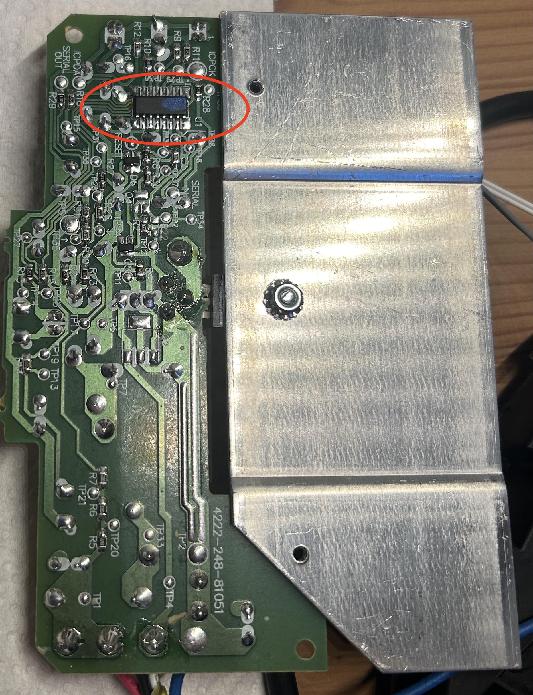 We’ve now seen quite some fundamental concepts from which most other elements are also built. We’ve seen MOSFET, CMOS logic, extensions into combinatorial logic, feedback, latches, clocks and lastly flip-flops. Now believe it or not, the small micro controller (the brain) of the Senseo machine packs even more stuff inside than just these. In fact, the core elements such as CPU, memory, GPIO (for LEDs) and ADC (boiler) are yet to come to the surface. Before going into the first element, let’s perhaps first finally set our sights on the long awaited microcontroller, which I myself have been looking for for ages. Philips had the good senses to completely hide it, not on a separate panel, but on the bottom of the PCB. Took me way longer than it should have to even screw it off and look there, though.
As you likely noticed in the above picture, the microcontroller has 7 legs (pins) on each side. This is perfect size for having 8-10 GPIO pins, an ADC channel (temparature sensing), timer, PWM (pump) and an internal oscillator. All of which we’ll see later on as well. Idea is just that these pins are the connection between the brain on the one hand, and on the other the PCB and appliance parts. When we press the power button, or 1/2 cup buttons, all this input is processed inside the MCU. Same goes for the temperature sensing. Meanwhile, the machine shows us LED lights that have a fixed meaning (blinking - brewing, fixed - ready) only because this tiny chip controls those lights. Both heater and pump do what they do, and when they do it, because the MCU directs them to.
CPU Core
Now onto the CPU. Due to our usage of complex computers we might think of it as the thinking or computing part, but it’s actually a pretty mundane thing physically. A CPU is essentially a large arrangement of flip flops and logic gates, driven by a clock. These then repeatedly rearrange stored values in a prescribed way (that’s where the designer’s programming comes in). What we want to know with the CPU is which stored voltages are allowed to overwrite which other stored voltages on the clock edge. Essentially, the CPU has three physical components:
- Registers: A group of D flip flops sharing the same clock. So each bit is charge being stored in a latch, reinforced by feedback and updated on a clock edge (‘the bits are in the register’).
- CMOS gates: used for combinatorial logic, as seen before. Essentially, between the registers there are adders, comparators and AND / OR / NOT networks; essentially a bunch of CMOS gates. Voltages from the register (array of flip flops) is taken and turned into new voltages.
- Clock: for defining when registers update. As before, all registers may updates on the clock edge, but here not all registers do, as we decide which by using logic gates. The CPU therefore behaves like edge-settle-edge-settle-…
Everything else in the CPU, like the ALU, control unit, program counters etc. aren’t new things but just a particular arrangement of registers and logic. Now because we’re getting so deep into the Senseo’s brain, it might prove worthwhile to link all this back to the actual functionings of the machine.
What we essentially want is to heat water, measure temperature (NTC thermistor), wait a specific amount of time until the buttons stabilize, and then have the actuators perform in the right order. Actuator refers to those parts that actually do something when powered, so the water pump, boiler, valves and LEDs. These need to be triggered in the right order for the machine to function well. This all comes down to the fact that the machine needs to have certain wires going high (1) or low (0) at a particular moment in time, continuing on past wire values. The CPU then exists to decide which stored voltages should change on each clock edge.
 In fact, the CPU performs something of a loop: it’s a clocked system that repeatedly reads a pattern of stored voltages, computes new voltages from them, decides which registers will accept those new voltages, and then copies them on the next clock edge. Now the CPU is split into roles that each answer very specific physical question. If we didn’t have such roles, and only the three physical components mentioned earlier, we’d have pure chaos as everything would try to update all the time.
CPU Sub-Systems
Program Counter (PC): tracks which step of behavior we’re in, where in the sequence we are at a particular moment. Physically, it’s made of a register (array of flip flops) whose output goes into an adder (logic gates seen in combinatorial logic) and a multiplexer.
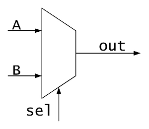 A multiplexer (MUX) is made out of CMOS gates and has the job of selecting between sources ~ taking multiple inputs and based on control lines, forwarding exactly one of them to the output. There’s rules about how many outputs take on how many inputs, but that’s not too relevant here. The idea is that each input is connected through transistors that can open or close, resulting in one path turning on at a time. A transmission gate then aides in this (again just transistors), and some logic gates then decode the select lines into turning this switch on and others off.
On each clock edge, we either get PC = prior PC + 1, or PC = another value (jump). In the Senseo this translates for instance to step 12: heat, step 13: check temperature, step 14: wait. Note that the Senseo has no idea about the meaning of the values, all it has is the 12, 13, 14, whose meaning is given in the control unit where instruction bits exist.
This sounds confusing, but let’s consider the PC purely physically. The main part of the PC is a register, which is just a bunch of D flip flops holding a binary number as voltages, and since it’s an array of flip flops, we may have e.g. 8 bits (binary digits) connected like ‘00010110’, which is just stored charge. This is connected to two places, an adder which takes a PC value and a constant value 00000001 and produces PC +1, and a multiplexer. The MUX has as input both the output of the adder (PC +1) and some other value called a jump target. The MUX then outputs into the PC register input (the D wire for the flip flops).
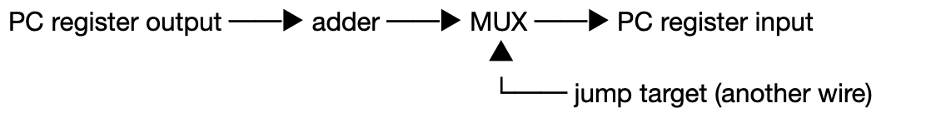
Now as briefly mentioned, the MUX has a select wire driven by the control unit (see below) that goes select = 0 we choose PC +1, and select = 1 we choose the jump target. This jump target is nothing special. When the Senseo is on, and we wait a little and hear the boiler running and the evolution of its simmering coming to a certain stop after which the light stabilizes, this essentially means the select wire has kept doing PC + 1. What’s happened during this period is that the machine has gone from 12 to 13 to 14 (heat - check temperature - wait, examples), but then it needs to go back to 12, so the select wire will switch on, and the jump target is chosen in the above circuit which brings the PC back to value 12. So the jump target is nothing more than PC loading a different value, like resetting the sequence (when we press the button to let coffee flow) or looping back. Physically it’s another set of wires carrying numbers, such as 00000000 for restart. PC capturing the MUX output again happens on the clock edge.
Instruction Register(IR): We’d like to know what needs to be done in a particular step, so the only real purpose of this part is to hold a pattern that controls behavior. It’s just another register, now loaded from the memory output (flash - see later) that holds a fixed voltage pattern for several cycles. This pattern has no purpose in and of itself, it only feeds logic. What happens is that PC outputs a certain value (address), and flash will respond to this by placing a certain voltage on its data wires. These wires are connected to the inputs of the IR, where on the clock edge those voltages actually go into the register of the IR. The output of this IR directly influences control logic (in the control unit), ALU control and MUX select logic. It doesn’t execute anything itself but does influence which wires are enabled later on.
Control Unit: this is the part that directs everything else. It fetches instructions, decodes them, and generates control signals. It’s the manager of the CPU, it stand between all other parts and makes everything do what needs to be done at the right time. Physically it’s combinatorial logic whose outputs decide which registers are allowed to copy on the next clock edge. So instruction bits (from the designer’s instruction memory) go in, current state bits go in and the logic gates produce a signal such as for instance ‘enable PC’, ‘enable register A’ or ‘write GPIO’ (see later). These signals go directly to transmission gates inside registers. Control in ‘control unit’ refers to the idea that on a certain edge, certain flip flops are allowed to accept new charge.
Now earlier on in the flip flop section we saw that a flip flop’s enable wire is the clock edge, so wouldn’t that imply that all flip flops are updated on the edge, not just a select few? What’s important to see here is that a register has more than just the clock coming in, each flip flop in a register is kind of gated. That way the D input isn’t always connected and instead passes through a transmission gate controlled by an enable signal. So there’s an additional wire influencing whether the flip flop gets influenced by the clock edge or not. For a flip flop to see the D signal, both the enable wire must be on and the clock edge must occur. These enable signals then come from the control unit itself.
ALU (Arithmetic Logic Unit): This is kind of the real calculator inside the Senseo, its sole purpose is to make calculations and produce new voltages from existing ones. Physically it’s a bunch of adders, comparators (similar combinatorial logic) and simple logic gates. It’s a purely reactive component, inputs change so outputs settle at a certain value. In Senseo its real job is tasks like comparing the ADC value with the threshold, computing timing counters and evaluating conditions. These results are never stored at the ALU, instead they’re only of consequence if a register (that array of flip flops) can capture them on a clock edge (the value of the ALU then comes through the D wire we saw before).
It may be an interesting exercise to explore what a full ‘CPU cycle’ looks like. Let’s say we want to turn on the heater if temperature < target (example we saw before in the boiler section), we then have the following activities in the CPU: (1) before the clock edge, the ADC result is stored in the register (flip flops), instruction bits (from the designer) are stored in another register, and the ALU output wires settle because it doesn’t yet have access to store it in the registers. (2) Next the control logic settles, the logic gates decide whether to write to GPIO (e.g. lamp we see stabilizes or not), update the PC (which step is taken next), and so on. (3) Now the clock edge happens, and selected registers copy voltages from their input (D), yet other registers remain unchanged. After the edge (4), we then have new voltages propagating throughout, and nothing else changes. This process then keeps repeating as long as the power is on.
CPU Supporting Systems
Then there are some other elements part of the CPU, but these are more on the supporting side. Working registers (register file) is just additional registers for general purpose, often selected via MUX. Additionally, a flag register (again just another register) exists so that once ALU outputs values that may influence decisions, e.g. result = 0, comparison of something, overflow, etc., the logic coming from those will set bits in the flag register. A flag may then be for instance Z (zero), C (carry) and so on, and these bits feed control logic and PC jump decisions. This may sound particularly vague, but physically, it’s a register like any other with say 4 flip flops in it: FF0 - FF1 - FF2 - FF3, which all just share a clock and have enable wires like any other register. Each flip flop stores one voltage either near GND or VDD (0 or 1). A bit being ‘flagged as Z’ is then nothing more than wiring, say we, the designer, choose to call FF0 flag Z and make it so that its D wire is attached to that logic coming from ALU = 0.
Interrupt logic further allows buttons, timers and safety signal to override the normal PC flow, it includes a comparator (combinatorial logic like adder) that detects an interrupt request and forces the PC select wire to jump. A flag will typically be set if this is used so that the CPU knows it was interrupted. Say we press the button to let coffee flow, this is then exactly the place something happens, and consequently influences the PC via the control unit’s combinatorial logic. Further, we’ve not really clarified this but the wires connecting all are called buses. The idea is that the wires used are grouped into shared buses that physically are just metal routings, often with a MUX for efficiency (and tri state drivers but that’s not too important here).
Notice that this is all just transistors arranged in all sort of manners, making logic gates, feedback, latches, flip flops, transmission gates, adders, comparators.