Senseo Boiler: Sensing Temperature
This post is part of the Senseo series:
- Senseo Prelude
- Senseo Electricity Basics 1
- Senseo Electricity Basics 2: Generation
- Senseo Electricity Basics 3: Grid to Wall Socket
- Senseo Boiler: Heat and Electricity
- Senseo Boiler: Sensing Temperature
- Senseo Boiler: Sensing Temperature Part 2
- Senseo Boiler: Safety
- Senseo Boiler: Brewing
- What is Plastic?
- PCB - Printed Circuit Boards: Fundamentals 1
- PCB Fundamentals 2: MOSFET Transistors
- PCB Fundamentals 3: CMOS Logic
- PCB Fundamentals 4: Combinational v Sequential Logic
- PCB Fundamentals 5: D-Latch
- PCB Fundamentals 6: Clocks & Flip-Flops
- PCB Microcontroller Subsystems: CPU core
- PCB Microcontroller Subsystems: GPIO
- Senseo GPIO Button Example
- PCB Microcontroller Subsystems: ADC (Conceptual)
- Senseo Interlude: Considering Quality
- PCB Microcontroller Subsystems: RAM and FLASH memory
NTC thermistor - metal pin entering side
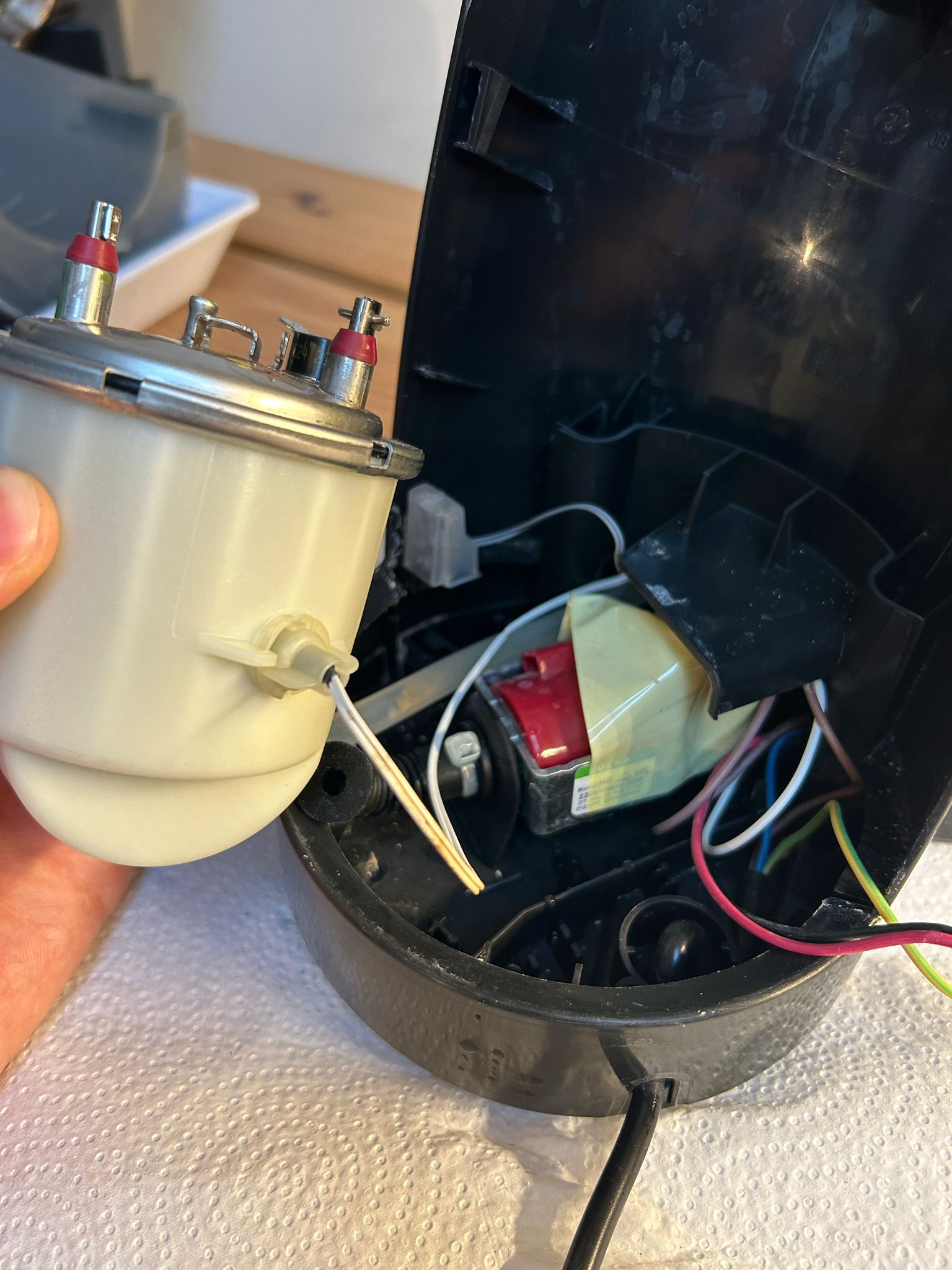 The obscure white wire entering the side of the boiler and having a long metal pin to it, is the temperature sensor of the Senseo (See both picture on the right and open boiler in Part 5). NTC stands for Negative Temperature Coefficient thermistor. The PCB (control board) needs this pin in order for the boiler not to overheat (as it has some 1000-1500W).
Inside the metal pin is an NTC bead, which is made from a specially made ceramic consisting of several metal oxides. This special ceramic has the property that when getting hotter, resistance goes down, while if colder the resistance goes up (that’s what NTC means). The change in behavior by this material is predictable and measurable.
The materials this ceramic bead (not the same type as pottery) is made of are engineered so as to make it sensitive to heat. In order to really understand this, I suppose we again must go to the atomic level of it all: most NTC thermistors are made of transition-metal atoms stuck together with oxygen atoms. These are metals such as Manganese (Mn), Nickel (Ni), Cobalt (Co) and Iron (Fe). The metals (M) are placed next to oxygen (O) and bind to become MnO (manganese oxide) and so on. So we can think of it like M-O-M-O-…, however, this chain is made to be imperfect on purpose, so that sometimes there is more metal than oxygen or vice versa and different metals in the chain will have different oxygenation levels (the atoms adapt so that the electric charge of the whole stays neutral). Because of the different oxygenation levels, electrons (that are normally stuck in place in these) can hop from atom to atom. This occurs because atomic imbalances force some metals to have extra electrons and others fewer, and as we’ve seen with electricity, imbalance causes electron movement.
Depending on the heat of the surrounding, this hopping will then be fast or slow (same idea as with water boiling). So the hopping that is made to be possible by design, is how electric current flows. The bead that is inside the metal sleeve on the picture is then made by mixing powders of metal oxides and shaping this into a tiny bead. This is then heated to make the atoms fuse into a sort of crystal ceramic. Wires are then attached so that the resistance can be measured.
These wires are used so that the bead can be sent electrical signals by the control board and the amount of current and voltage coming back can be measured. The control board therefore measures the temperature. So two electrical contacts are needed on the bead in order to get and receive signals. Wires are made of nickel or platinum because this bonds well with the ceramic and doesn’t get damaged by the boiler temperatures. In manufacturing, this wire is actually attached to the bead before the atoms are heated, so that in baking the ceramic, the wires are baked into it as well.
The functioning of this NTC sensor therefore starts with the control board, which sends a very small probe signal through it, and based on the resistance (from the possible heat) It figures out how much the signal changes and converts this into a temperature number.
What we essentially have is a voltage divider (see more later), which we should imagine to be on the path from the electricity source (eg. 5V) to the ground (0V). It has two resistors on that path, meaning there are two spots where something is placed that hampers the flow (current) of the electrons, yet still the same flow of charges goes through both. This current still reaches it’s destination, but the pressure which is behind their movement gets hampered a little (voltage). This voltage divider is quite difficult to grasp, so let’s slow way down and built it up from voltage in batteries, single resistor circuits and then double resistor circuits.
Before we do that, though, let’s ground the idea of what’s happening in order to measure the resistance of the bead. The control board has power (eg. 5V) going to the first resistor. This first resistor is just a regular one as we saw before, placed on the control board itself. From that resistor, a wire goes to the NTC bead, making this bead the second resistor in the series. After the bead, the wire is connected to ground (reference V). So in the voltage divider we’ll see in more detail, the NTC is R2.
Extending knowledge of Voltage
At it’s core, without analogies or anything, voltage is just the difference in electric potential between two points, which is why ground is often used as reference (0V). This way if we for instance have a lamp connected to a battery (DC), the lamp’s input side has an electric potential of for instance 1.5V higher than its output side, and the lamp itself functions as a resistor. This voltage drop is the energy loss per electron when passing through the resistor. This is where the pitfall of it all lies for me, I’ve come to understand that electrons are being pushed through the wire by voltage, but in reality, they’re being pulled through the entire loop by the voltage difference between the terminals. This is why, when the electron gets to the lamp’s output side, which is at 0V since that’s the reference chosen for the node coming after the lamp’s output, it’s still being pulled to the terminal at 0V. It’s driven around the entire closed loop through global voltage difference, not local. There exists a pressure difference between the battery terminals, so electrons are pushed out the one side and pulled into the other side regardless of local voltage on the wire. Voltage is created between the two terminals, not at one side. That’s because this ‘global voltage’ actually creates an electric field on the wire, which is in turn the agent driving the supposed push and pull.
In batteries, something that hasn’t come up until now is the fact that the actual naming convention states that the negative side is labeled 0V, while the positive side is for instance +9V. This isn’t because there is less electrons at negative, it’s just a naming convention to label the difference in electric potential between the two sides. One of the two is 0V just as a reference to the other. Here lies the crux though, we have electron flow going from negative to positive, but the ‘conventional current’ goes from positive to negative. Why did people choose this opposite direction, you ask? Good question, for it confused me as well. When Benjamin Franklin guessed what was flowing through wires, he guessed it were positive charges and that they moved from the positive to the negative terminal (electrons hadn’t been discovered). Electrical engineering started using this convention, so when the electron was discovered it was too late to change all the fundamental infrastructure (circuit theory, engineering equations etc.).
Kirchhof’s law is what lies at the base of this all, and says that energy charges around a loop sum to zero. In the battery, we can take node A to be the negative terminal, which is labeled 0V (reference). If we go from negative terminal to positive terminal inside the battery, we see a difference of +9V, meaning the positive side is 9V higher in potential than node A (no electrons are moving). If we look outside of the battery, where a wire attaches the terminals and on that wire is a lamp, we travel in the direction of the conventional current (for the sake of Kirchhof’s law making sense). During this conventional current, the electrons hypothetically moving from positive to negative find the lamp resisting the current and the electrons lose energy there (9V-9V=0). As such we go in a loop, from 0V—>9V—>0V.
Now that the idea of voltage is cleared up, that electrons move to the other end of the circuit regardless, the idea of voltage dividing becomes clearer as well. When we have two resistors in series on a circuit, we still have that every electron reaches its destination, and therefore enter and pass both resistors. Current for both resistors is identical. We can already see what happens to voltage if we look at Ohm’s law, but let’s do it intuitively. Resistors demand a certain energy loss per electron. Since the atoms of the material from which a resistor is made (like tungsten in old lamps) vibrate as a result of electrons trying to flow through, the electrons lose energy. As such, more resistance means losing more energy during travel and vice versa. Now the battery has a fixed supply of energy per electron (say 9V), so we know from Kirchhof’s law that the total energy loss for both resistors must be 9V.
The electrons then lose energy in proportion to the resistance in each resistor. This we can view intuitively: With two resistors, electrons must push through both, but the battery is still supplying the same push as with the single resistor, so on average, the drift speed (current) will be lower when the electrons get hampered in multiple places. Now these resistors share current because the same electrons pass through both, and obstacles slow them down to a rate that keeps both satisfied.
Drift speed in general isn’t chosen freely, it’s determined by total resistance. This is saying the exact same thing, more resistance is lower drift speed so lower current. So if I have a single resistor on a circuit, a lamp, then the current is higher, meaning that in the lamp, there will be more collisions per second which leads to more energy lost. That’s how it drops the full 9V. If I have a lamp and then further on another resistor, then current is lower (electrons move slower) and as such fewer collisions happen per second, leading to less energy loss and so a smaller voltage drop for the lamp. This happens because, in case of a battery, the connection of the two terminals via wire create an electric field on the wire that depends on both the fixed supply the battery gives as well as the resistance on the wire. When resistance is higher, the electric field that ends up established on the wire becomes weaker. When adding resistance, the distribution of the electric field must adapt to satisfy the new total resistance.
Voltage Divider
Now with the voltage divider, we can again imagine a battery with a wire and two resistors. The battery has 9V, meaning that electrons travel through the wire while losing 9 Joules per Coulomb of energy, which is lost somewhere between the two resistors. Electrons pass both these resistors, so flow rate must be the same for both (determined by this electric field) and so is lower than if there were just one resistor.
Now each resistor converts electrical energy into heat, and the amount of energy lost per electron is proportional to its resistance. With higher resistance there’s more collisions and so more energy lost per electron. Since the current is the same for both resistors, the electrons lose some energy in R1 and some in R2, of which the total energy loss is the 9 J/C. If R1 resists twice as much as R2, electrons lose twice as much energy passing through R1, meaning there is a voltage split of 2:1 (R1 takes up 6V, R2 3V). This division is forced by how much energy each resistor demands from every electron passing through.
We can use Ohm’s law to make this clearer: Current (I) = Voltage (V) / Resistance (R), or otherwise V= I * R. So if we have the same exact current flowing through both, then the resistance in one compared to the other determines the amount of voltage taken up by either.
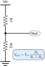 Since the battery gives us 9V (Joules per Coulomb), the energy lost in each resistor sums to 9 J/C, so the energy divides between the two. If we apply this proportionality idea to dividing the lost energy, we see that energy lost per electron in each resistor is proportional to its resistance. The equation we see here is that of the voltage divider. It calculates the output voltage (across R2) from both the input voltage and the proportion of resistance per resistor. If we therefore look at the node between R1 and R2, we find the electric potential after the electrons have already lost energy (voltage drop) corresponding to R1. Our voltage-out is therefore found in the middle, showing the remaining energy per electron (that we know to be dropped by the second resistor).