Senseo Boiler: Sensing Temperature Part 2
This post is part of the Senseo series:
- Senseo Prelude
- Senseo Electricity Basics 1
- Senseo Electricity Basics 2: Generation
- Senseo Electricity Basics 3: Grid to Wall Socket
- Senseo Boiler: Heat and Electricity
- Senseo Boiler: Sensing Temperature
- Senseo Boiler: Sensing Temperature Part 2
- Senseo Boiler: Safety
- Senseo Boiler: Brewing
- What is Plastic?
- PCB - Printed Circuit Boards: Fundamentals 1
- PCB Fundamentals 2: MOSFET Transistors
- PCB Fundamentals 3: CMOS Logic
- PCB Fundamentals 4: Combinational v Sequential Logic
- PCB Fundamentals 5: D-Latch
- PCB Fundamentals 6: Clocks & Flip-Flops
- PCB Microcontroller Subsystems: CPU core
- PCB Microcontroller Subsystems: GPIO
- Senseo GPIO Button Example
- PCB Microcontroller Subsystems: ADC (Conceptual)
- Senseo Interlude: Considering Quality
- PCB Microcontroller Subsystems: RAM and FLASH memory
NTC thermistor - Bringing it all together
This NTC thermistor for the boiler of the Senseo machine is placed on the control board in a series of two resistors. In fact, it’s the second resistor in that series where the first is a fixed chosen one (though depending on design the NTC could also be the first). So when the control board sends a fixed DC reference voltage (input voltage) to the divider, the concept of this voltage division is used to measure the voltage drop after the first fixed resistor. Knowing the voltage that remains at a node in the middle means that we know the voltage remaining for the NTC.
For instance if the Senseo control board powers the divider 5V, and that divider has R1 (fixed resistor of 10 kΩ) and R2 (NTC, changing with temperature). Using the picture visual at the end of last post, we see the control board measures the middle point.
Now if that NTC is cold, there’s lots of resistance, since like with atoms of water, cold makes them move slower and in this case lets electrons go from metal to metal slower. Let’s therefore use the example where the cold NTC has 10 kΩ. When the boiler is heated, however, electrons move faster, and NTC becomes 2 kΩ. In the case of the cold NTC, we use the divider formula: V-out = 5V * R2/(R1+R2), so 5V * 10k/(10k+10k) which is 2.5V. This out-voltage is what the microcontroller sees.
When the NTC is warm, we again use the equation and see V-out = 5V * 2k/(10k+2k) which is 0.83V. This makes intuitive sense, when the NTC is warm, it has little resistance, so it drops a smaller shares of the total voltage.
We haven’t really seen this yet as it’s for one of the next sections, but the Senseo machine makes use of a microcontroller with 10-bit ADC, which reads 0-5V. Essentially this ADC just has the task of saying what fraction of the 5V it’s seeing. This voltage is expressed as a digital value, between 0 and 1023. What the control board then does is convert the V-out it got from the divider into the actual thermistor resistance using the inverse of the voltage divider equation (see equation below).

By simple calculation for our example, we find for a warm boiler for instance the resistance of (10kΩ * 0.83V/(5V-0.83V)) = 1.99 kΩ (or 1990 ohms, same as the 2 kΩ from before). In reality, the voltage divider equation is used only in reverse, not forward as before. The controller directly reads the V-out voltage as a number between 0-1023 from the ADC, and then uses the inverse equation to transform this into resistance. The ADC knows how to read the voltage from V-out because it has a built in reference voltage and merely compares the two and outputs a digital value. The firmware essentially converts the ADC to V-out by (V-out = (ADC/1023)*V-ref). So with reference of 5V, an ADC read as 409, we find the 2V. This is then used in the inverse voltage divider equation to get the resistance.
Next, it turns that resistance into temperature, which can be done in several ways. The easiest is a temperature lookup table (contained by the firmware), which goes from resistance 10000 Ω being 25 °C to resistance 900 Ω being 90 °C. Now the Senseo doesn’t use this as it isn’t very accurate. It instead uses the Beta equation for this conversion, which also takes into account the material (used also in kettles, boilers, dishwashers etc.). It relates the temperature to the thermistor resistance by deriving exponential behavior of semiconductor conduction (which the NTC bead is).
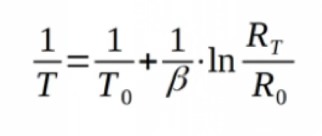
Beta: Is here actually just a constant, determined by the thermistor material (between 3000-4500K).
T: Temperature in Kelvin, taken into account both at T0 (so when cold) and the warm temperature.
Rt: Resistor at temperature T
R0: Resistance at reference temperature T0, which for 25 °C is 298.15K.
For instance, at the NTC being 25 °C and having 10 kΩ, we have the R0 = 10000 Ω with T0 = 298.15K. We take a typical beta value of 3950K (summary of physics in the bead). Then at any measured resistance we can easily compute the temperature. For our heated boiler of R = 2.0 kΩ, we have 1/T = 1/298.15 + 1/3950 * ln(2k/10k), which is T = 339.4K, being 66.2 °C.
In order to already have some context since these topics will only be thoroughly explored in other sections: The Senseo machine has firmware in it, which is to say there is software stored inside the machine that tells it things like when to heat, how hot to make it, when to pump water and so on. The microcontroller is then a computer chip inside the Senseo, it uses the firmware (instructions) and controls the machine. There is then also the control board (PCB), which is to be considered like the body with all the wiring, it connects all the parts and lets the firmware actually do things.
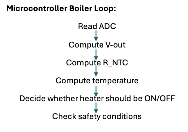
So what happens is that the microcontroller (the brain for which firmware is the memory) constantly runs a loop (see below) where it goes through all the steps for the boiler. There are then two main temperature thresholds, T_low and T-high, which form a band between them in order to have ON/OFF. So below T_low (≈85°C) the heater is ON and water warms up, and once temperature goes above T_high (95°C), the heater gets turned OFF. This is what’s called a hysteresis band, which implies that between T_low and T_high, the system doesn’t react to small changes and the output remains stable (no constant ON/OFF switching). This hysteresis band is the same concept used for the A/C and explains why cooling to 21°C in reality means that the room temperature will drop to 19°C, where it stops.
When I turn on my Senseo machine, therefore, what happens is that the water is cold, likely around 20°C, and the heater is turned on continuously. This because the microcontroller is running its loop of steps constantly (10-100x a second). As such, electrons flow through the Nichrome wire, but are resisted in such a way to cause heat release. The temperature touching the metal sleeve which the ceramic bead is in rises, eventually causing such low resistance that the microcontrollers reads the voltage divider and converts this to a temperature crossing 85-90°C. Whenever this happens, the heater is switched OFF, and the light I see on the frond becomes steady. If I then don’t press the button, eventually the constant loop detects a temperature that is again under the threshold, and starts heating again (or the machine falls out).
Some safety checking also exist, among which the next two sub-sections are devoted, but inside the microcontroller we here already have some minor ones. For one, if the microcontroller detects temperature of 100-105°C, it will shutdown the heater and give warning, while if between 110-120, there will likely be an emergency shutdown, and power to the boiler is completely shut off.
There’s also the dry-boil detection, where the machine knows I didn’t put water in it. The way the microcontroller detects this is because the temperature will rise too quickly. So if it jumps from 50°C to 90°C, the firmware detects this rate of rising and immediately stops the heating to avoid damaging the boiler. There are some other safety checks, but I think these are the most interesting ones.
Semiconductors
This ceramic bead is essentially a semiconductor, a topic that might be relevant to understand since LED lamps are this as well (though very different kinds). We’ve seen conductors, like copper, aluminum and so on, which let through electrical current quite easily without resisting it. On the other hand there is insulation, like the Magnesium Oxide powder in the boiler tube (or glass, plastic, etc), which completely block the flow of electrons yet do transfer heat. A semi-conductor sits right in-between the two, and doesn’t let electrons flow like metal but also doesn’t completely block them. In fact, semi-conductors change how it behaves with regards to electrons based on the conditions (temperature, light, etc.). LED’s are a bit more complex than this small section warrants, so might be for another day.